By Chris Carrillo, April Labonte, Scott Larson, Don Gudeczauskas, Colin Poedtke, and Pat Valentine PhD
Uyemura International Corporation
Southington, CT
Abstract
Reduction-assisted immersion gold (RAIG) baths have excellent viability but are not universally used due to poor bath stability. Taking advantage of the benefits of the RAIG process enables world-class quality "on target with minimal variation." This study focuses on improving bath stability using non-hazardous compounds while meeting industry standards and requirements for final finishes.
The next-generation RAIG provides excellent bath stability, enhanced corrosion resistance at thicker gold deposits, robust solderability and wire bonding, reducing scrap costs and increasing reliability. The overall research consisted of an in-depth literature review, design of experiments (DoE), corrosion evaluations, solderability tests, wire bond pulls, and statistical analysis.
Introduction
Hyper-corrosion of the electroless nickel deposit caused by traditional immersion gold baths has plagued the electronics industry since the creation of electroless nickel/immersion gold (ENIG), see Figure 1. The electroless nickel/electroless palladium/immersion gold (ENEPIG) finish was thought of as the industry-wide answer to end hyper-corrosion by adding an electroless palladium layer, but that has not been the case.[1] Hyper-corrosion has been known to cause manufacturing defects that prevent world-class quality "on target with minimal variation."
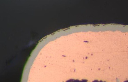
Figure 1. Nickel Hyper Corrosion from Traditional Immersion Gold Electrolyte.
The Institute for Interconnecting and Packaging Electronic Circuits (IPC) developed a rating system to quantify acceptable levels of nickel hyper-corrosion.[2] Advancements in plating chemistry technology have reduced the prevalence of hyper-corrosion; however, it remains a concern in the electronics industry.[3] Research developments in electroless plating chemistries have led to the invention of reduction-assisted immersion gold (RAIG) electrolytes.[4]
In a RAIG electrolyte, a mixed reaction occurs by a displacement reaction followed by an autocatalytic reaction induced by a reducing agent. This allows the RAIG electrolyte to minimize the displacement reaction while meeting or exceeding the maximum gold thickness capabilities of immersion gold electrolytes. Conventional immersion gold electrolytes function by corroding the nickel-phosphorus deposit. The nature of this mechanism limits the thickness of a gold layer that can be produced without nickel hyper-corrosion. Despite the advantages of RAIG electrolytes, they have not been widely adopted in the electronics industry.[4]
The primary challenge with implementing RAIG in the electronics industry is the stability of the electrolyte. With conventional immersion gold electrolytes, the deposition reaction stops when no substrate atoms are available, increasing stability. Since RAIG electrolytes have a reducing agent, a continuous deposition loop can form, decreasing bath stability. Increasing electrolyte stability will drastically increase the adoption of RAIG in the electronics industry.
To maintain stability, first-generation RAIG electrolytes required a hazardous stabilizer to be dosed periodically. Hazardous stabilizers, such as potassium cyanide, present a serious health risk.[5] Safety concerns continue to impede the implementation of first-generation RAIG. A novel RAIG formulation addressing stability and safety concerns can enable the electronics industry to meet world-class quality "on target with minimal variation.”
Experimental Methodology
Reliability testing enables a thorough investigation of a plating electrolyte's overall robustness and stability. The responses measured in the reliability testing were gold electrolyte stability, thickness distribution, nickel hyper-corrosion, solderability, and wire bondability. The testing was performed on PCBs plated with 0.05 and 0.1 μm of gold for ENIG and ENEPIG applications. These gold thicknesses are commonly seen in the PCB industry for RAIG electrolytes. Reliability tests are an efficient and statistically sound method to study process robustness, with the experimenter choosing the responses to measure.
The test boards used in this study consisted of a copper-clad FR-4 substrate plated to a thickness of 20 μm using an acid copper electroplating process. The copper-plated substrate was coated with a solder mask and imaged to form a plated through hole with a 300 μm diameter annular ring for worst-case scenario corrosion testing. A J-STD-003D W coupon on the test boards was used for the wetting balance and edge dip active wetting testing.[6] A wire bond coupon on the test board was used for wire bond testing. An example of the test board is shown in Figure 2.
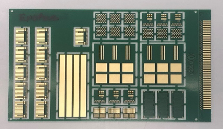
Figure 2. Test Coupon.
The optimum concentration of the non-hazardous stabilizing agent was determined through lab testing. Several months of field use, throughout the electrolyte’s functional life, corroborated the lab concentration results. The electrolytes were evaluated using both direct and indirect heating. The tanks were routinely inspected for gold plate out.
A Bowman M-series XRF was used to evaluate the thickness distribution on the test coupon. Thickness uniformity was measured on 1.5x1.5 mm pads per IPC-4552B and IPC-4556 AM-1.[2, 7] Thickness uniformity was also evaluated on five different pad sizes ranging from 170 mm2 grounding pads to 0.15 mm2 SMT pads. The coefficient of variance percentage (CV) for each test run was calculated and recorded.
A Leica model DMi8 metallograph was used to evaluate the corrosion product rating on the test coupon. The corrosion coupons were mounted in epoxy using a 5:1 resin-hardener ratio for two hours. The cross-sections were prepared per IPC-TM-650 Clauses 5.3.2 and 5.3.4.[8] The plated through holes were evaluated for corrosion per IPC-4552B.[2] The corrosion product rating for each test run was recorded.
A DDM Novastar GF 125HC reflow oven was used to stress the test boards for 2x reflows at 250°C peak temperature per J-STD-003D before solderability testing.[6] A Microtronic LBT210 was used to test the solderability of the RAIG finish. A SAC 305 solder alloy was used for wetting balance, edge dip active wetting, and solder float solderability tests in conformance with J-STD-003D.[6] Time to buoyancy corrected zero, and maximum wetting force was recorded for wetting balance. Positive advancement of solder was recorded for edge dip active wetting, and pass/fail criteria were recorded for solder float testing.
Wire bonding coupons were stressed for 16 hours at 175°C in air. A Palomar 9000 Wedge Bonder machine was used to bond 1.0-mil aluminum wire to the 0.05 μm ENIG plated test board. A Palomar 8100 Wire/Ball Bonder machine was used to bond 1.0-mil gold wire to the 0.05 μm ENEPIG plated test boards. Twenty wire bonds were formed on each test board. Wire bond pull strength was tested per MIL-STD-883 Method 2011, Condition D.[9] Both gram-pull break forces and locations were recorded. The failure modes were evaluated using scanning electron microscope/energy dispersive spectroscopy (SEM/EDS).
Scanning electron microscope images allow for high resolution and increased depth of focus compared to optical microscopes.[10] Energy dispersive spectroscopy analysis allows for the detection and distinction of different elements based on the X-ray energy generated by the sample.[11] Scanning electron microscope/energy dispersive spectroscopy was used to analyze intermetallic (IMC) layer, solder joint and wire bond integrity. The ability to gather high-resolution images at increased magnification aids in optimizing solder joint and wire bond reliability. Statistical analysis was completed on the data collected.
Minitab© 21 was used for statistical analysis. Individual distribution identification and multivariate charts were the primary tools used to analyze the data–the tools allowed for analyzing the stability and reliability of the RAIG electrolyte.
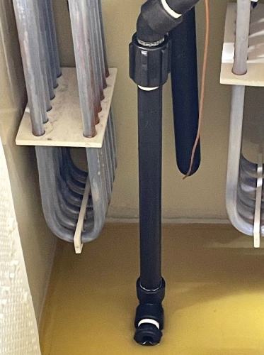
Figure 3. End-of-life plating tank condition.
The gold plating thicknesses of 0.05 μm and 0.1 μm were targeted. The distribution of gold for both ENIG and ENEPIG surface finishes were analyzed. The testing included using a mid-phosphorus electroless nickel and a palladium phosphorous electroless palladium for ENIG and ENEPIG samples. Five thickness measurements were taken from five pads of various sizes on the test vehicles. The dimensions of these pads are shown in Table 1.
| Table 1. Dimensions of SMT Pads Used for Distribution Study. | ||
|---|---|---|
| Pad Shape | Pad ID | Dimension |
| Square | 1 | 13 x 13 mm |
| 2 | 1.5 x 1.5 mm | |
| Rectangle | 3 | 20 x 1 mm |
| 4 | 2 x 0.5 mm | |
| 5 | 1 x 0.15 mm | |
The thickness of both the electroless nickel and palladium layers on the test vehicle were verified to meet IPC-4552B (ENIG) or IPC-4556-AM-1 (ENEPIG) specifications respectively.[2, 7] The results indicated that the novel RAIG electrolyte produces a uniform deposit for ENIG and ENEPIG applications with a CV of less than 4%, see Table 2. The gold electrolyte displays excellent uniformity for ENIG and ENEPIG applications at nominal and elevated gold thickness targets, see Figures 4 and 5. Next, corrosion analysis was performed.
| Table 2. Distribution Results. | ||
|---|---|---|
| Run | Au Thickness (μm) | Au CV (%) |
| ENIG, 0.05 μm | 0.06 | 1.98 |
| ENIG, 0.1 μm | ENIG, 0.1 μm | ENIG, 0.1 μm |
| ENEPIG, 0.05 μm | 0.05 | 3.71 |
| ENEPIG, 0.1 μm | 0.09 | 2.34 |
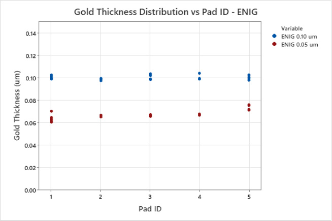
Figure 4. ENIG Multivariate Chart of Gold Thickness and Pad ID.
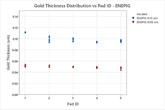
Figure 5. ENEPIG Multivariate Chart of Gold Thickness and Pad ID.
| Table 3. Corrosion Product Ratings. | ||||
|---|---|---|---|---|
| ENIG | ENEPIG | |||
| Au Thickness (μm) | 0.05 | 0.10 | 0.05 | 0.10 |
| IPC-4452B Corrosion Product Rating | 0 | 0 | 0 | 0 |
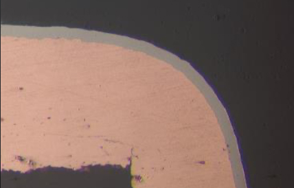
Figure 6. 0.10 μm ENIG Cross section.
Solderability testing was performed for each of the plated samples. For wetting balance testing, solder wetting times and maximum wetting forces all passed J-STD-003D.[6] Wetting balance results showed no practical difference regarding maximum wetting forces for the ENIG and ENEPIG samples. As expected, wetting balance results showed that ENEPIG samples had faster wetting times than ENIG samples. Wetting balance test results are shown in Table 4. Next, edge dip testing was completed.
| Table 4. Solder wetting balance test results. | ||||
|---|---|---|---|---|
| ENIG | ENEPIG | |||
| Au Thickness (μm) | 0.05 | 0.10 | 0.05 | 0.10 |
| Wetting Time (sec) | 2.64 | 2.30 | 1.19 | 1.78 |
| Wetting Force (mN/mm) | 0.22 | 0.21 | 0.21 | 0.21 |
Edge dip testing was performed for each of the plated samples. Edge dip results showed no evidence of non-wetting or de-wetting per J-STD-003D.[6] Positive advancement of solder greater than 1.55 mm was observed on all plated samples. Edge dip test results are shown in Table 5. Next, solder float testing was completed.
| Table 5. Edge dip test results. | ||||
|---|---|---|---|---|
| ENIG | ENEPIG | |||
| Au Thickness (μm) | 0.05 | 0.10 | 0.05 | 0.10 |
| Positive Advancement (mm) | 2.28 | 2.28 | 2.28 | 1.94 |
Solder float testing per J-STD-003D was conducted for each plated sample.[6] All plated through-hole knees were wetted entirely with solder. A scanning electron microscope was used to evaluate the integrity of the IMC after solder float testing for both ENIG and ENEPIG. Figures 7 and 8 show a contiguous IMC encased in a solder. Next, wire bond testing was completed.
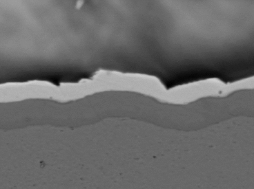
Figure 7. Contiguous IMC – ENIG.
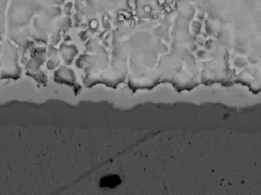
Figure 8. Contiguous IMC – ENEPIG.
Wire bond tests were conducted, and the results were analyzed per MIL-STD-883 Method 2011, Condition D for ENIG and ENEPIG surface finishes.[9] The 0.05 μm ENIG aluminum wire bonding resulted in an average of 9.6 grams force, exceeding the minimum pull force of 2.5 grams. The ENIG wire bond break conditions exhibited were heel breaks, all of which are acceptable failure modes, see Table 6 and Figure 9. Next, ENEPIG wire bond testing results were analyzed.
| Table 6. ENIG Aluminum Wire Bond Results. | |||||
|---|---|---|---|---|---|
| Finish | Pull Avg. (g) | Pull Test Mil-STD 2.5g | Bond Lift Count | Heel Breaks Count | Wire Breaks Count |
| ENIG | 9.6 | PASS | 0 | 20 | 0 |
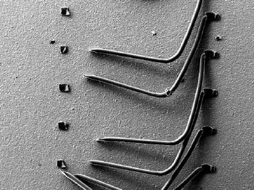
Figure 9. ENIG Wire Bond Failure Mode.
The 0.05 μm ENEPIG gold wire bonding resulted in an average of 12.3 grams force, exceeding the minimum pull force of 3 grams. The ENEPIG wire bond break conditions exhibited were heel and neck, all of which are acceptable failure modes, see Table 7 and Figure 10. The RAIG electrolyte provided a surface finish that greatly exceeded the minimum requirements for wire bonding for both ENIG and ENEPIG. The performance of the novel RAIG electrolyte is discussed in the conclusion.
| Table 7. ENEPIG Gold Wire Bond Results. | |||||
|---|---|---|---|---|---|
| Finish | Pull Avg. (g) | Pull Test Mil-STD 2.5g | Bond Lift Count | Neck Breaks Count | Wire Breaks Count |
| ENEPIG | 12.3 | PASS | 0 | 20 | 0 |
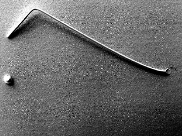
Figure 10. ENEPIG Wire Bond Failure Mode.
Conclusions
Reduction-assisted immersion gold electrolytes have superior performance compared to conventional immersion gold electrolytes but are not universally used due to poor bath stability. Traditional RAIG electrolytes require a hazardous stabilizer, such as potassium cyanide, to maintain stability, which presents health and safety concerns. This paper evaluated a novel RAIG formulation that uses a non-hazardous stabilizer without compromising performance. The novel RAIG electrolyte was assessed for reliability and yielded the following results:
- Gold plate-out was eliminated with the use of the non-hazardous stabilizing agent.
- Excellent gold thickness uniformity for both ENIG and ENEPIG applications.
- Corrosion product ratings of zero per IPC-4552B.[2]
- Solderability testing, including wetting balance, edge dip, and solder float, all passed per J-STD-003D.[6]
- Wire bonding for ENIG and ENEPIG exceeded the minimum requirements per MIL-STD-883 Method 2011, Condition D.[9]
Improving the stability of RAIG electrolytes significantly impacts the electronics industry. The next-generation RAIG provides excellent bath stability, enhanced corrosion resistance at thicker gold deposits, robust solderability, and wire bonding, reducing scrap costs and increasing reliability. The use of the non-hazardous stabilizing agent eliminates any health and safety concerns. Taking advantage of the benefits of the next-generation RAIG process enables world-class quality "on target with minimal variation."
References
[1] Yao W., Wu D., Xiao Z., Wang Y., Yang R. (2019). Acceleration Effects of Hydroxylamine Sulfates on Electroless Gold Plating on Ni-Pd Surfaces.
[2] IPC – Institute for Interconnecting and Packaging Electronic Circuits (2016). Specification for Electroless Nickel /Immersion Gold (ENIG) Plating for Printed Circuit Boards (Standard No. IPC-4552B). Bannockburn, Illinois: IPC
[3] Accogli, A., et al. (2020). Understanding the Failure Mode of Electroless Nickel Immersion Gold Process: In Situ-Raman Spectroscopy and Electrochemical Characterization.
[4] Schafsteller, B., Rosin, M., Schlosser, T., & Ramos, G. (2022). Mixed Reaction Gold as Versatile Plating Solution for ENIG, ENEPIG and EPIG Plating.
[5] Schafsteller, B., Spreemann, R., Tews, D., & Ramos, G. (IPC APEX EXPO 2023). Enabling KCN-Free Stabilization for Mixed Reaction Gold Electrolytes.
[6] IPC – Institute for Interconnecting and Packaging Electronic Circuits (20122).Joint Industry Standard Solderability Tests for Printed Boards (Standard No. IPC-STD-003D). Bannockburn, Illinois: IPC
[7] IPC – Institute for Interconnecting and Packaging Electronic Circuits (2016). Specification for Electroless Nickel/Electroless Palladium /Immersion Gold (ENEPIG) Plating for Printed Circuit Boards (Standard No. IPC-45526 AM-1). Bannockburn, Illinois: IPC
[8] IPC – Institute for Interconnecting and Packaging Electronic Circuits (2015). Test Methods Manual (Standard No. IPC-TM-650). Bannockburn, Illinois: IPC
[9] MIL-STD – U.S. Department of Defense Test Method Standard (1996). Microcircuits. (Standard No. MIL-STD-883).
[10] Dr. Jun Jiao, Scanning Electron Microscopy. Portland State University.
[11] IXRF SYSTEMS, Introduction to Energy Dispersive Spectroscopy. Uyemura internal training.
Biography
Chris Carrillo is a Senior Technical Service Engineer for Uyemura USA. He holds a Bachelor’s of Science Degree in Chemical Engineering from California State Polytechnic University in Pomona with a Minor in Materials Engineering, and is a Six Sigma Black Belt. Chris can be contacted at ccarrillo@uyemura.com.
April Labonte is a Western Regional Technical Manager for Uyemura USA. She holds a Bachelor's of Science Degree in Chemical Engineering from the University of California San Diego, and is a Six Sigma Black Belt. April can be contacted at alabonte@uyemura.com.
Scott Larson is a Technical Service Engineer for Uyemura USA. He holds a Bachelor’s of Science Degree in Chemical Engineering from Lehigh University, and ASQ certification as a Six Sigma Black Belt. Scott can be contacted at slarson@uyemura.com
Colin Poedtke is a Technical Service Engineer for Uyemura USA. He holds a Bachelor’s of Science Degree in Chemical Engineering from the University of Illinois Urbana-Champaign, and is a Six Sigma Black Belt . Colin can be contacted at cpoedtke@uyemura.com.
Don Gudeczauskas is Vice President at Uyemura USA, where he has been employed for the last 27 years. Don has a Bachelor's and Master’s degree in Metallurgical Engineering from the Colorado School of Mines, and is a Six Sigma Black Belt. Don can be contacted at dgudeczauskas@uyemura.com.
Patrick Valentine is the Technical and Lean Six Sigma Manager for Uyemura USA. He holds a Doctorate Degree in Quality Systems Management from Cambridge College, a Six Sigma Master Black Belt certification from Arizona State University, and ASQ certifications as a Six Sigma Black Belt and Reliability Engineer. Patrick can be contacted at pvalentine@uyemura.com.