By George Milad
Uyemura International Corporation
Southington CT
Introduction:
The North American printed circuit business continues to adjust to the ever changing landscape of global market conditions. Initial problems with supply chain management are being continuously addressed and sorted out. Most OEMs are finding it advantageous to manufacture their more established big runners and their customary and off the shelf (COTS) products, in the Far East particularly in China.
There are certain categories of products that remain in North America. These are primarily the prototype boards, the large backplane (>40 layers), and the boards for military use. Boards with new proprietary designs that require the respect of intellectual property are kept in the USA. OEMs in the medical field continue to use US manufacturing on their products that are used in life sustaining devices and require the highest level of reliability over time.
The prototype boards require elaborate front-end engineering to bring the part to its final configuration in a reasonable time frame. Prototype boards are never made in numbers, but they may go through a series of iterations before finalization. These boards cover a wide range of complexity with some being highly sophisticated with high layer count, small holes, and buried and blind laser drilled vias. Less than 3 mil lines and spaces and “Via Fill” were first encountered in the prototype shops.
The backplane type boards may reach a thickness of 400 mils, and although the holes are usually >20 mils, it is the highest aspect ratio demand. Boards with aspect ration >20:1 are manufactured and plated today. This is one of the highest value added products in PCB manufacturing.
To meet these specification requirements the board shop is forced to seek new and advanced processes in every department in the manufacturing process. Acid copper plating comes under heavy scrutiny, as it is the process that forms the traces and the “thru hole” connectivity that convey the signal from end to end of the final device.
The uniformity of thickness distribution on the surface and in the holes is becoming ever more challenging as board designs continue down the path of smaller holes and finer lines as well as the need for impedance control. Surface uniformity is sometimes plagued with the occurrence of nodules, which come from a variety of sources. Gold wire bonding applications have no tolerance to any level of nodulation.
In addition, there is a greater demand on the physical properties; tensile strength and elongation (T&E) of the plated copper, to withstand the rigors of high temperature assembly of Lead Free (LF) solder as required for ROHS compliance.
New developments are helping meet this challenge. A big part of the developments are focused on:
- New chemical additive packages for improved thickness distribution.
- Mass transfer improvements to compliment the additives
- Nodules elimination by use of insoluble anode
- “Via Filling”, a specific application
Acid Copper Organic Additives:
Acid copper additives fall into three main categories:
- Carriers
- Brighteners
- Levelers
Carriers increase the polarization resistance and are current suppressors. The suppression is a result of the carrier being adsorbed to the surface of the cathode; which in turn gives rise to an increase in the effective thickness of the diffusion layer. Suppression causes the deposit grain structure to be more uniform and adherent. The carrier modified diffusion layer also improves plating distribution without burning the deposit.
The brightener is a grain refiner. Its adsorption produces a film that will suppress crystallographic differences. Brighteners may be adsorbed preferentially on particular active sites such as lattice kinks, growth steps, or tops of cones, or surface projections; growths at these locations are then blocked. Brighteners give rise to fine grained structures that are equiaxed with no specific direction. A fine grained structure is a bright structure. The brightener is the component that has the maximum effect on the final copper physical properties, namely tensile strength and per cent elongation.
Levelers or leveling agents are inhibitors present at low concentrations in the electrolyte as compared to the depositing metal. In case of a micro profile the diffusion layer does not follow the profile contour, but is maximum at the valleys and minimum at the peaks. Consequently, in absence of a leveling agent, depositing ions diffuse more rapidly to the peaks than to the valleys, and deposits grow more rapidly on the peaks, resulting in an exaggerated profile. With good solution agitation, the leveler will accumulate more rapidly and readily at the peaks and it will inhibit growth or deposition. The absence of leveler in the valleys will allow faster deposit growth and allow the valleys to catch up to the peak, thus creating leveling.
Pulse Plating:
For the last few years the copper plating industry was focused on pulse plating and in particular periodic pulse reverse, as the solution for all. As time progressed and the level of difficulty continued to climb, the plating current density for pulse began to drop and the primary advantage of plating at higher current density began to disappear. Add to that the complexity of operating a pulse rectifier with added definition of ASF, forward to reverse ratio, duty cycle and waveform. In many instances pulse also required an elaborate and frequent scheme of organic regeneration to maintain the copper thickness distribution benefits.
Most pulse plating of printed circuit boards today is done at very low current densities and for extended plating times, many pulse cycles include a series of ever changing pulse plating parameters. Most of the advantages attributed to pulse plating are more the result of plating at low ASF for extended periods of time (up to four hours) rather than the effect of pulse rectification.
High Throw DC Plating:
A new generation of “High Throwing Power” acid copper systems have come to the market to fill the void. These baths are designed for today’s plating currents, which are lower than the traditional 25 - 30 ASF, which was common in the days of double-sided, and simpler products.
High throw baths are designed to give the desired physical properties at current densities as low as 5 ASF and as high as 20 ASF. They produce bright ductile deposits.
These bath types are characterized by a specific combination of organic additive package that includes a unique leveling agent. The leveler plays a key role in improving throwing power particularly if it is coupled with a well designed solution movement system with or without air.
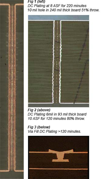
Some of these baths can give a throwing power >80% for a 12:1 aspect ratio drilled hole plating 1.0 mil in the hole, in a plating time of 90 minutes, in a vertical dip tank mode.
Fig 1 shows a 24:1 aspect ratio hole plated at 8 ASF (DC) for 220 minutes with 51 % throw. Fig 2 shows a 15:1 aspect ratio hole plated at 10 ASF (DC) for 120 minutes with 80% throw.
Mass Transfer:
Mass transfer becomes a key parameter that must be understood and managed for high aspect ratio plating. An example is plating a 400 mil thick board with 20 mil holes diameter a 20:1 aspect ratio, a 93mil thick board with 6 mil holes, or a 125 mil thick board with 8 mils holes, both 15:1 aspect ratios. Mass transfer is also critical for plating a blind via with an aspect ratio greater >1.0.
Mass transfer is influenced first and foremost by diffusion, also affected by solution agitation, and part or rack agitation. Of course a reduction in plating rate will always improve distribution by maximizing the role of diffusion for mass transfer.
Diffusion refers to the movement of ions through the solution in response to a concentration gradient. It is a consequence of random molecular motion that operates to produce more uniform distribution throughout the solution. As soon as plating begins to deplete the copper ions in the immediate vicinity of the cathode (in the diffusion layer) diffusion drives more ions in to equalize the concentration. If the plating rate is higher than the rate of diffusion alternate sources of “mixing” must be used to avoid burning the deposit.
Eductors:
Eductors are used today in many of acid copper plating tanks. They create turbulent solution flow without the use of air sparging. The design and layout of the eductor sparging system is important to maximize the solution shearing action at the surface for the board to be plated. If properly designed eductors can preclude the need for part agitation. The increased solution flow at the surface as compared to the middle of the hole could be effective in improving the throwing power, provided the chemical additives used are designed to respond preferentially to solution movement. Eductors eliminate the need for compressed air or air blowers, and also provides a safer environment where acid is not constantly been blown into the air, or the exhaust system.
Nodule Elimination Insoluble Anode:
The use of insoluble anodes is well established in the acid copper conveyorized equipment. It offers a series of advantages over the conventional copper slugs/balls in titanium baskets. The most prominent advantage is the absence of copper anodes, which need to be filmed and bagged to contain naturally occurring sludge from getting on the work.
Anodes, even in their purest form, are prolific sources of suspended matter that leads to nodules. Insoluble anodes eliminate the need for dummy plating to film the anode. The need for standard anode maintenance is also eliminated. The anode shape and dimensions are not altered throughout the life of the insoluble anode.
The insoluble anode requires a continuous supply of copper ions brought into the system from an external source. Some of the methods used to generate copper are the dissolution of copper oxide into the electrolyte, the electrolytic dissolution in an external rectified cell and the use of ozone to oxidize copper metal in an adjunct device.
The elimination of anode maintenance, the consistency of the anode area and the elimination of the soluble anode as a source of nodulation make the use of the insoluble anode a viable solution for the plating challenges today.
Via Fill Plating
To meet the demands of high density interconnect, “via filling” is quickly becoming a clear choice for connecting the different layers in buildup technology (stacked vias and vias in pad) manufacturing. They result in an overall improvement in long-term reliability of the PCB and the package.
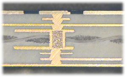
Suppliers have developed new electrolytes for plugging vias shut. Both pulse plating and DC plating proprietary “Via Filling” chemistries are available in the market place. DC plating offers a series of advantages as it does not require pulse rectification and avoids the complexity of managing a pulse wave. In addition DC plating systems are stable and do not require the constant regeneration of pulsed electrolytes. The use of DC plating allows the filling of most blind vias to be completed in under 120 minutes depending on the degree of difficulty or aspect ratio.
Via Filling is based on high depositing ion concentration coupled with a unique additive package that is composed of carrier and brightener, with a low concentration of a leveling agent. Most of these systems require optimized highly uniform, solution flow. The flow allows the leveler to accumulate on the surface, thus inhibiting plating while the bottom of the via continues to plate. The plating dynamics in the bottom of the hole are very different than those on the board surface. Eventually as the hole fills, the difference in plating dynamics even out. Figure 3 show DC plating of a via using completed in under 2 hours.
Acid copper plating has come a long way since the early days of double and single sided Printed Wiring Boards. Plating challenges will continue to increase as new product demands (lighter smaller and more reliable) come to market. As one leading edge milestone is conquered, a new one is set. Stay tuned.